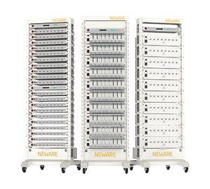
● Battery materials research
● 3C products
● Power/energy storage cells (Power tools, Electric vehicles and etc.)
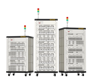
● Electric vehicles
● Communication base stations
● Energy storage and other battery pack
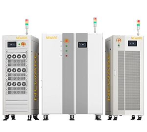
● Electric bus
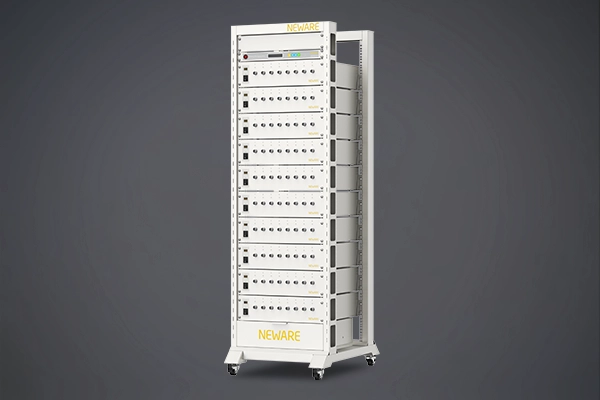
● Large energy storage battery pack
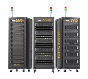
● Power/energy storage cells (Power tools, Electric vehicles, Energy storage cells and etc.)
● Battery materials research
● 3C products
● Power/energy storage cells (Power tools, Electric vehicles and etc.)
● Battery materials research
● 3C battery research and etc.
5V / 6V / 10V / 20V
5V
5V / 6V / ... /
500V / ... / 1000V
5V / 10V / 20V /
24V / 30V
5V
10mA / ... / 100mA /
6A / 12A
100mA / 20A / 30A /
... / 500A / ... /
1500A
20A / 30A / 40A /
60A / ... / 600A /
... / 1200A
100mA / 10A / 15A /
... / 75A / ... /
1200A / ... / 7200A
5A / 6A / 6.5A /
12A / 13A
AD: 16bit
DA: 16bit
AD: 16bit / 24bit
DA: 16bit
AD: 24bit
DA: 24bit
AD: 16bit
DA: 16bit
AD: 16bit
DA: 16bit
0.1mV / 0.1mA
0.1mV / 0.1mA
0.1mV / 0.1mA
0.1mV / 0.1mA
0.1mV / 0.1mA
≥1MΩ / ≥1GΩ / ≥100kΩ
≥100kΩ / ≥1MΩ
≥1MΩ
Main channel ≥ 1MΩ
Auxiliary channel ≥ 200kΩ / 1GΩ
≥1000MΩ Startup state (shutdown leakage current is 100 μA)
Energy feedback function (energy saving)
—
Supports: ≥65% (Full load)
Not support for linear power supply solution
Supports:
>75% (Full load)
>90% (Full load)
>94% (Full load)
Supports: ≥80% (Full load)
Not support for linear power scheme
—
≥99% (Full load)
≥99% (Full load)
≥99% (Full load)
≥99% (Full load)
≥99% (Full load)
-5V / 0V / 1V /
1.5V / 2V / 2.5V
0V / 2.5V
-10V / 1.7V / 3V /
5V / 10V / 30V
-5V / -3V / 0V /
1.5V / 2.5V
-5V / 0.7V
± 0.01% F.S.
± 0.02% F.S.
± 0.05% F.S.
± 0.1% F.S.
± 0.01% F.S.
± 0.02% F.S.
± 0.05% F.S.
± 0.01% F.S.
± 0.02% F.S.
± 0.05% F.S.
± 0.02% F.S.
± 0.02% F.S.
± 0.01% F.S.
± 0.02% F.S.
± 0.05% F.S.
± 0.1% F.S.
± 0.01% F.S.
± 0.02% F.S.
± 0.05% F.S.
± 0.01% F.S.
± 0.05% F.S.
± 0.01% F.S.
± 0.01% F.S.
Current range segmentation
Single range
Three ranges
Four ranges
Three ranges
Four ranges
Single range
Single range
Three ranges
Four ranges
Multi-ranges
Four ranges
± 0.02% F.S.
± 0.05% F.S.
± 0.1% F.S.
± 0.02% F.S.
± 0.05% F.S.
± 0.05% F.S.
± 0.02% F.S.
± 0.03% F.S.
± 0.05% F.S.
± 0.02% F.S.
Constant voltage cut-off current
Each independent range* 0.2%
Each independent range* 0.2%
Each independent range* 0.1%
—
—
± 0.02% F.S.
± 0.05% F.S.
± 0.1% F.S.
± 0.02% F.S.
± 0.05% F.S.
± 0.05% F.S.
± 0.025% F.S.
± 0.01% F.S.
± 0.015% F.S.
± 0.025% F.S.
± 0.01% F.S.
Single-channel maximum power
Voltage * Current
Voltage * Current
Voltage * Current
Voltage * Current
Voltage * Current
± 0.03% F.S.
± 0.5% F.S.
± 0.1% F.S.
± 0.1% F.S.
± 0.05% F.S.
± 0.02% F.S.
± 0.05% F.S.
± 0.01% F.S.
≤20ms / ≤500μs / ≤1ms
≤5ms / ≤10ms
≤3ms / ≤5ms
≤20ms / ≤30ms / ≤1ms
≤100μs
Charging and discharge conversion time
≤40ms / ≤25ms
≤20ms
≤6ms / ≤10ms
≤20ms / ≤30ms / ≤2ms
35ms
100ms (10Hz)
10ms (100Hz)
10ms (100Hz)
The auxiliary channel is 10Hz
10ms (100Hz)
1ms (1000Hz)
Voltage range * 0.2%
Voltage range * 0.2%
Voltage range * 0.2%
—
Voltage range * 0.2%
Each independent current range * 0.2%
Each independent current range * 0.2%
Each independent current range * 0.2%
—
—
Charge and discharge mode
● Constant current charge and discharge
● Constant voltage charge and discharge
● Constant current constant voltage charge and discharge
● Constant power charge and discharge
● Pulse charge and discharge
● Constant resistance charge and discharge
● Follow mode charge and discharge and etc.
● Constant current charge and discharge
● Constant voltage charge and discharge
● Constant current constant voltage charge and discharge
● Constant power charge and discharge
● Pulse charge and discharge
● Constant resistance charge and discharge
● Follow mode charge and discharge and etc.
● Constant current charge and discharge
● Constant voltage charge and discharge
● Constant current constant voltage charge and discharge
● Constant power charge and discharge
● Pulse charge and discharge
● Constant resistance charge and discharge
● Follow mode charge and discharge and etc.
● Constant current charge and discharge
● Constant voltage charge
● Constant current constant voltage charge and discharge
● Constant power charge and discharge
● Constant power constant voltage charge and discharge
● Pulse charge and discharge
● Constant resistance discharge and etc.
● Constant current charge and discharge
● Constant voltage charge
● Constant current constant voltage charge and discharge
● Constant power charge and discharge
● Constant power constant voltage charge and discharge
● Pulse charge and discharge
● Constant resistance discharge and etc.
Voltage, Current, Relative time, Capacity, -△V and etc.
Voltage, Current, Relative time, Capacity, -△V and etc.
Voltage, Current, Relative time, Capacity, -△V and etc.
Voltage, Current, Relative time, Capacity, Energy, -△V, Custom variables, and etc.
Voltage, Current, Relative time, Capacity, Energy, -△V, Custom variables, and etc.
Pulse
Pulse / Condition
Pulse / Condition
Condition
Pulse / Condition
Charge/discharge mode (pulse/condition)
Constant current mode
Constant power mode
Constant current mode
Constant power mode
Constant current mode
Constant power mode
—
Constant current mode
Constant power mode
Minimum Pulse Width (pulse/condition)
500ms
100ms / 500ms
100ms
—
400μs
A single pulse step supports 32 different pulses
A single pulse step supports 32 different pulses
A single pulse step supports 32 different pulses
—
A single pulse step supports 16 different pulse segments
Continuous switch of charge and discharge (pulse)
A pulse step can realize the continuous switch from charge to discharge
A pulse step can realize the continuous switch from charge to discharge
A pulse step can realize the continuous switch from charge to discharge
—
A pulse working step can realize continuous switching of charge, or continuous switching of discharge
Cut-off condition (pulse/condition)
Voltage, Relative time
Voltage, Relative time
Voltage, Relative time
—
Voltage, Number of pulses, Working time
Do not support
Support
Support
Support
Support
Support
Support
Support
Support
Support
Greater than 50A supports four-channel parallel connection
Supports a maximum of two adjacent channels in parallel
Parallel connection of up to 4 channels is supported.
Pulse and simulation tests are not supported after parallel connection
Energy saving devices of 75A and higher support parallel channels
Do not support
65535
65535
65535
65535
65535
≤3 layers
≤3 layers
≤3 layers
≤4 layers
≤4 layers
Edit the number of work steps in a single process
Software/hardware protection
● Power down data protection
● Offline testing
● Voltage upper/lower limits
● Current upper/lower limits
● Capacity limits
● Delay time
● Reverse connection protection
● Custom variable protection
● Overvoltage protection
● Overvcurrent protection
● Overtemperature protection
● Emergency stop protection
● Power down data protection
● Offline testing
● Voltage upper/lower limits
● Current upper/lower limits
● Delay time
● Reverse connection protection
● Overvoltage protection
● Overvcurrent protection
● Overtemperature protection
● Power down data protection
● Offline testing
● Voltage upper/lower limits
● Current upper/lower limits
● Delay time
● Reverse connection protection
● Overvoltage protection
● Overvcurrent protection
● Overtemperature protection
● Input over voltage protection
● Output overvoltage protection
● Input over current protection
● Output current protection
● Overheating protection
● Overload protection
● Output empty load protection
● Power down data protection
● Offline testing
● Reverse connection protection
● Voltage upper/lower limits
● Current upper/lower limits
● Delay time
● Capacity limits,
● Energy upper limit
● Control parameter out-of-tolerance protection
● Current/voltage fluctuation protection
● Voltage slope protection
● Delay protection
● Auxiliary voltage protection
● Auxiliary temperature protection
● Input over voltage protection
● Output overvoltage protection
● Input over current protection
● Output current protection
● Overheating protection
● Overload protection
● Output empty load protection
● Power down data protection
● Offline testing
● Security conditions seting
● Reverse connection protection
● Voltage upper/lower limits
● Current upper/lower limits
● Delay time
● Capacity limits
● Energy upper limit
● Control parameter out-of-tolerance protection
● Current/voltage fluctuation protection
● Voltage slope protection
● Delay protection
● Auxiliary voltage protection
● Auxiliary temperature protection
Protection level IP20
Protection level IP20
Protection level IP20
Protection level IP20
Protection level IP20
● Constant current source and constant voltage source adopt double closed-loop structure
● Constant current source and constant voltage source adopt double closed-loop structure
● Constant current source and constant voltage source adopt double closed-loop structure
● Constant current source and constant voltage source adopt double closed-loop structure
● Supports parallel connection of any adjacent channel
● Supports fault-tolerant operation (shielding fault channels)
● Energy Saving Inverter Technology, Energy flow locally between channels
● Adopt automotive main control scheme, 200kHz high-frequency conversion
● Low ripple noise, Small volume, Low energy consumption and heat production
● Constant current source and constant pressure source using independent double closed loop structure
● Integrated system design, the unit machine directly connects to the test server
● 100Hz high speed sampling
● 1GB offline storage capacity per channel
● Constant current source and constant voltage source adopt double closed-loop structure
Individual control
Individual control
Individual control
Individual control
Individual control
Voltage and current detection sampling
Four wire connection
Four wire connection
Four wire connection
Four wire connection
Four wire connection
<85dB
<75dB
<55dB
<45dB
<65dB
<75dB
<65dB
<75dB
<80dB
<85dB
<80dB
Using MySQL database to manage test data
Using MySQL database to manage test data
Using MySQL database to manage test data
Using MySQL database to manage test data
Using MySQL database to manage test data
Communication mode of host computer
Based on TCP/IP protocols
Based on TCP/IP protocols
Based on TCP/IP protocols
Based on TCP/IP protocols
Based on TCP/IP protocols
Excel, Txt
Excel, Txt
Excel, Txt
NDA, Excel (customized export way of circulation layer, work layer, record layer, diagram, self- defined report), TXT, CSV
NDA, Excel (customized export way of circulation layer, work layer, record layer, diagram, self- defined report) , TXT, CSV
Windows 7, Windows10 or above
Windows 7, Windows10 or above
Windows 7, Windows10 or above
Windows 7, Windows10 or above
Windows 7, Windows10 or above
● Network interface
● Support CAN
● RS485 and BMS communication
● Support DBC configuration function (optional)
● Network interface
● Support CAN
● RS485 and BMS communication
● Support DBC configuration function (optional)
● Ethernet network
● Support CAN
● RS485 and BMS communication
● Support DBC configuration function (optional)
● Network interface
● Multiple machines extend communication through switches and routers (optional)
● Network interface
● 0℃ ~ 40℃ (in the range of 25±10℃, guaranteeing testing accurancy with fluctuation of 0.005% F.S. /℃)
● 0℃ ~ 40℃ (in the range of 25±10℃, guaranteeing testing accurancy with fluctuation of 0.005% F.S. /℃)
● -10℃ ~ 40℃ (in the range of 25±10℃, guaranteeing testing accurancy with fluctuation of 0.005% F.S. /℃)
● 25±10℃ / 25±5℃ (guaranteeing accurancy)
● 25±20℃ (limiting usage temperature)
● 25±5℃ (guaranteeing accurancy)
● 25±20℃ (limiting usage temperature)
-10℃ ~ 50℃
-10℃ ~ 50℃
-20℃ ~ 50℃
0℃ ~ 45℃
0℃ ~ 60℃
Relative humidity range of the working environment
≤70% RH (No condensation)
≤70% RH (No condensation)
≤70% RH (No condensation)
30% ~ 80% RH (No condensation)
≤70% RH (No condensation)
Relative humidity range of the storage environment
≤80% RH (No condensation)
≤80% RH (No condensation)
≤80% RH (No condensation)
30% ~ 90% RH (No condensation)
≤80% RH (No condensation)
Note:Whether to support battery test with a protection plate
Not available when the voltage ≥20V
Not available when the voltage ≥20V
Not available
Available
Available