FAQ is designed to assist users in swiftly resolving issues encountered during software installation, device usage, and testing processes. They ensure adherence to correct procedures, thus providing the most accurate measurement results possible.
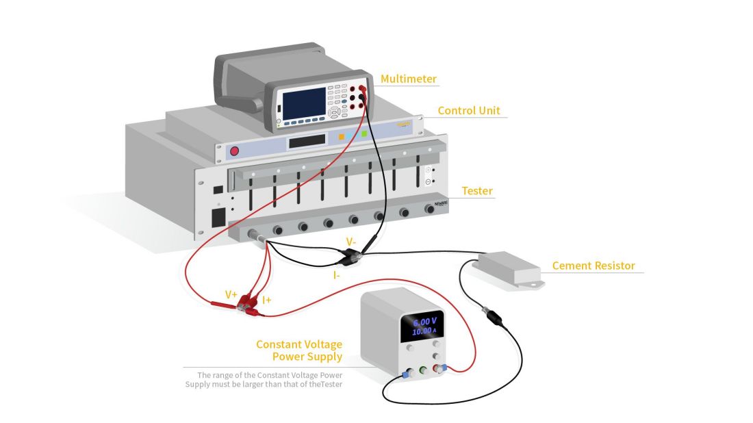
First, connect the power cables of the multimeter, Control Unit, and Tester.
1.2 Connecting the network cable
Connect the Control Unit to the Tester using a network cable. The Control Unit is connected to the switch. The multimeter is connected to the switch.
Finally, connect the switch to the computer using a network cable.
1.3 Connecting the multimeter and the Tester
Next, connect the multimeter test line, red represents the positive pole and black represents the negative pole.
The red wire is connected to the positive terminal. The black wire is connected to the negative terminal. Connect the fixture to the Tester and tighten it.
Connect the fixture to the test wire on the multimeter.
1.4 Start the device and check the multimeter IP
After powering on the device, start the Tester, Control Unit, and multimeter in turn.
Then click Shift key, Display key, I/O key, LAN Settings key. You can view the multimeter IP address.
Press Shift and DCV to switch to DCI mode. The multimeter screen displays the current unit.
1.5 General Setup Section of the Computer
1.5.1 Turning off protection and firewalls
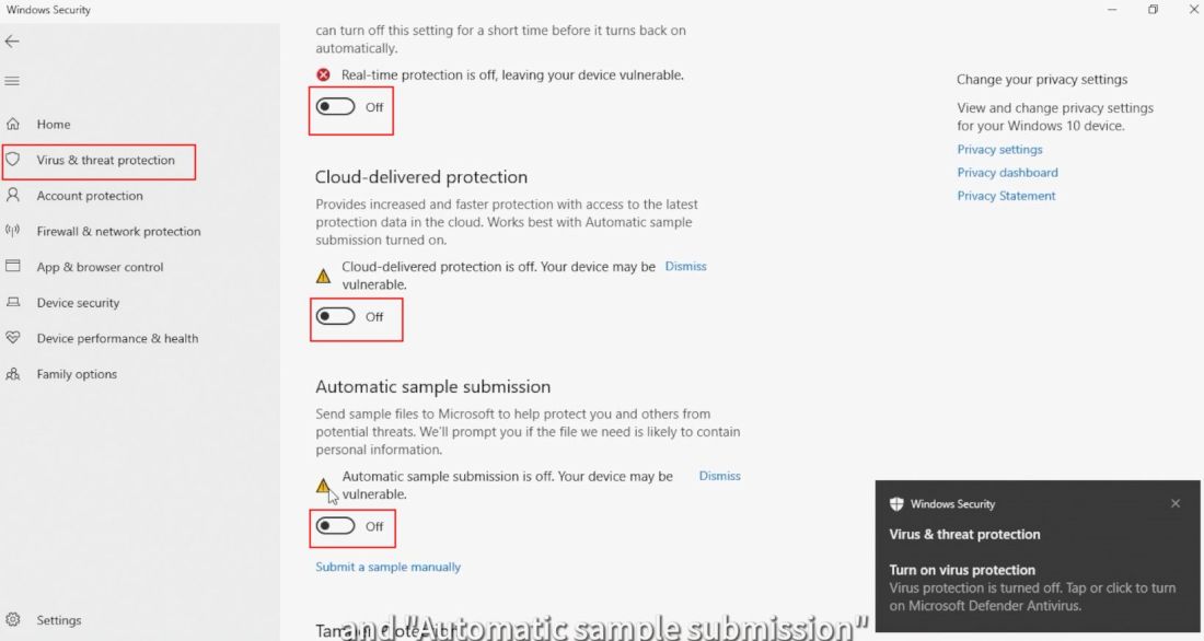
Enter Windows Security. Find "Manage settings" under "Virus & threat Protection".
Turn off "Real-time protection", "Cloud-delivered protection", and "Automatic sample submission".
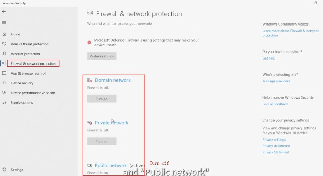
Click on "Firewall & network protection" in the left column. Turn off "Domain network", "Private network", and "Public network".
1.5.2 Setting the computer IP
First, access the "Control Panel". Click on "Network and Internet" and then proceed to the "Network and Sharing Centre". In the left column, click on "Change adapter settings".
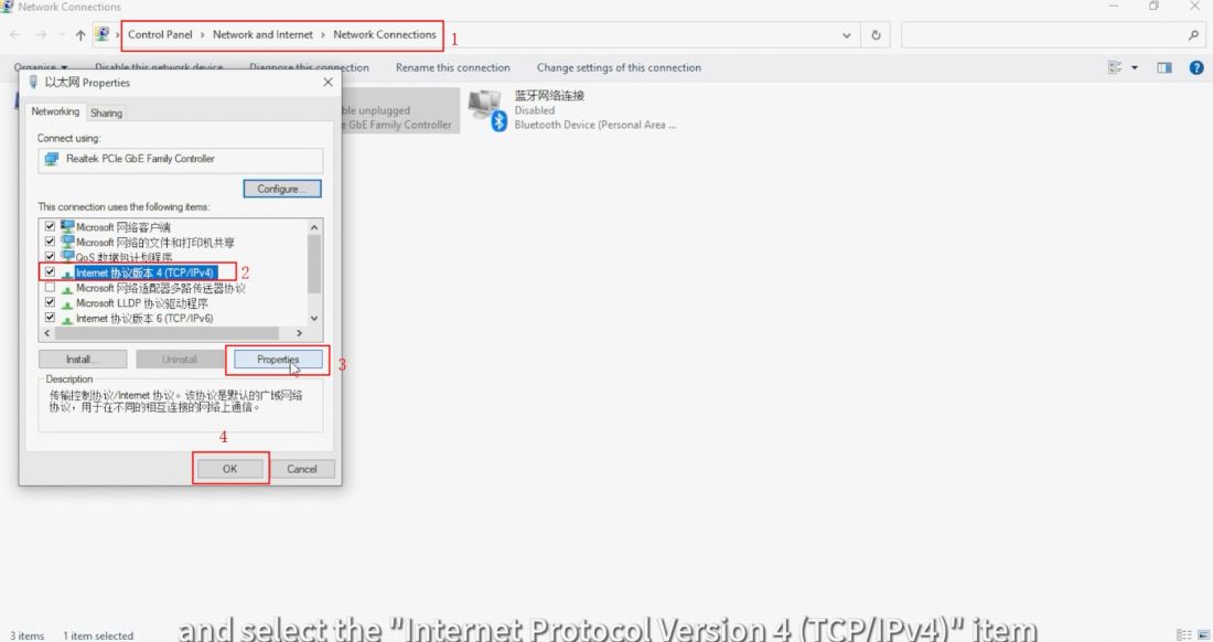
Right-click on "Ethernet", select "Properties", and choose the "Internet Protocol Version 4 (TCP/IPv4)" item.
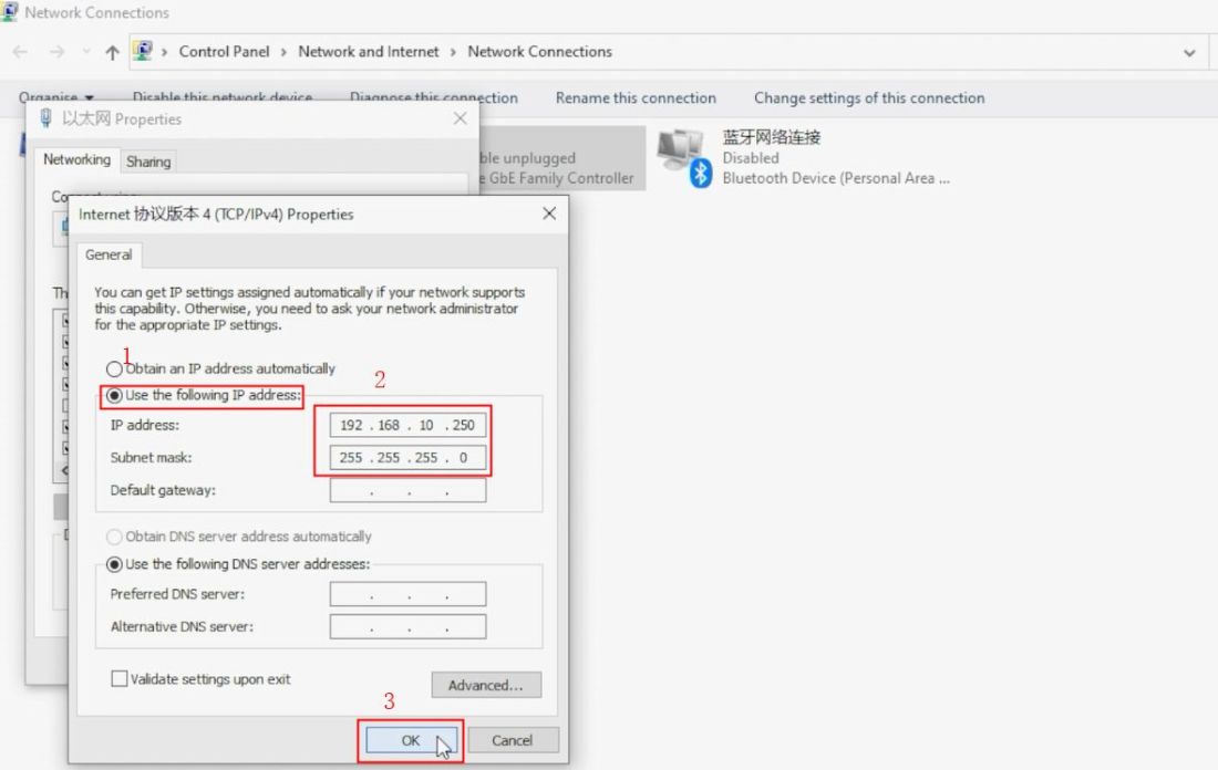
Click on "Properties" and select "Use the following IP address". Manually enter the IP address as "192.168.10.250". It is important to note that the IP address must match the IP address of the Control Unit server.
Click on the input box for "Subnet mask" to automatically detect the mask address.
Finally, click "OK" and then click "Close".
1.6 Guidance on BTS software operation
1.6.1 User login and channel mapping
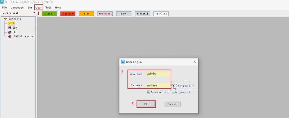
Open BTS software, click "User", select "User log in". The user name is "admin" and the password is "neware".
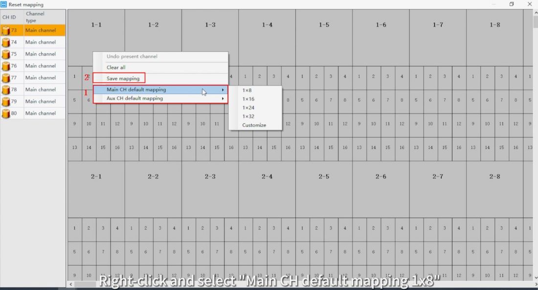
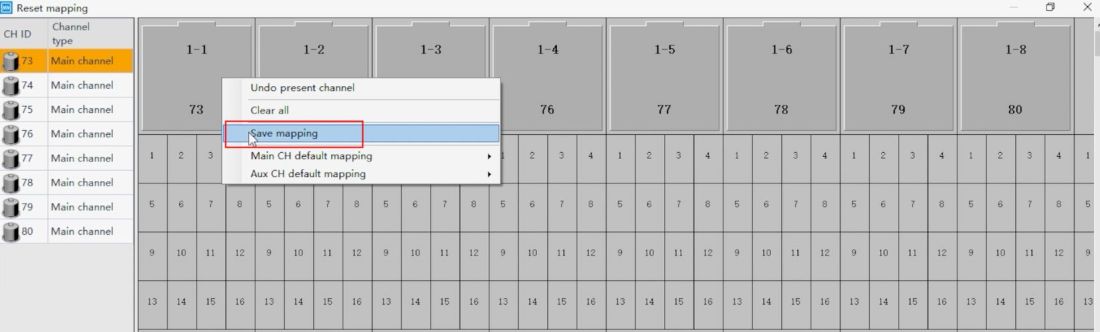
Right-click in the blank area and select "Reset mapping". Right-click and select "Main CH default mapping 1x8". Then right-click to save the mapping.
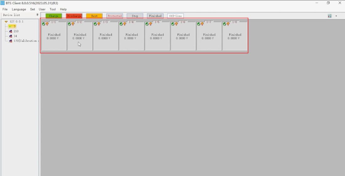
The software interface displays 8 test channels.
Click on "Tools" and select "Calibration". After clicking "Connect", the channel and multimeter IP will be displayed in the left column. Ensure that the multimeter IP address is the same as that on the multimeter display.
If the IP address of the multimeter is not displayed, click "Connect" again.
Click "System configuration" and select "Standard connection settings" . You can view and modify the multimeter's IP address here. Confirm that the following two options are unchecked, then click "OK".
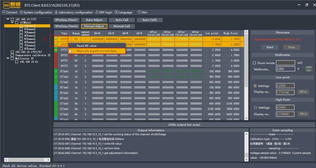
Select "Manual-Adjust" and then select the channel that you want to calibrate (shown here as channel 1). This is the calibration current, so double click "CC(mA)".
After successful selection, a yellow arrow is displayed before the option.
And then click Start. Enter the multimeter reading at this time into the "Multimeter Value" box, noting the conversion unit. Then click "Fill in" next to "Display Value" in the "Low Point" box below.
Then click Start. Enter the current multimeter reading into the "Multimeter Value" box. Click "Fill in" next to "Display Value" in the "High Point" box below.
Do this in turn and complete all current calibration items.
1.6.3 Calibration CC (mA)
When the device is not equipped with a negative power supply, an external power supply is required for calibrating "DC(mA)".
If the device serial number includes the letter 'F', it indicates that the device comes with a negative power supply; otherwise, it does not.
The hardware connection mode is shown in the figure, and the software operation is the same as calibrating "CC(mA)".
2. Manually calibrate voltage
2.1 Replacing Wiring
Replace the red wire on the multimeter into the Input jack.
Then, connect an external cement resistor. Attach the crocodile clamps to the two ends of the cement resistor and the positive and negative probe terminals of the multimeter respectively.
Next, switch from DCI mode to DCV mode, and the units on the screen will change to voltage.
Also select "Manual-Adjust" and then select the channel that you want to calibrate (shown here as channel 1). This calibration is for voltage adjustment, so double-click the "CV(V)" option.
Upon successful selection, a yellow arrow will be displayed next to the option.
Now, click "Start". Enter the current multimeter display value in the "Multimeter Value" box, noting the conversion unit. Then click "Fill in" next to "Display Value" in the "Low Point" box below.
Afterward, click "Start". Enter the current multimeter reading into the "Multimeter Value" box again. Click "Fill in" next to "Display Value" in the "High Point" box below.
Repeat these steps for all the current calibration items.
2.2.2 Calibration DV(V)
To calibrate DV, you need to connect a constant voltage power supply in series, as shown in the figure. The software operation is the same as calibrating "CV(V)".
3. Exported data
Select the completed items, and right-click to manually export the current data.